
The Critical Elements Of Construction Blueprints Los Angeles
UNPACKING THE CONCEPT OF CONSTRUCTION DRAWINGS
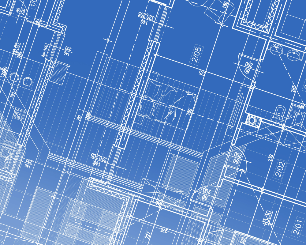
Construction blueprints are detailed visual representations used for various projects, whether they are residential, commercial, industrial, or public works. These blueprints not only guide the building process by illustrating the structure’s dimensions, plumbing, electrical systems, mechanical details, and material installations but also play a pivotal role in securing the necessary permissions from local authorities.
Typically, architects are responsible for producing the entirety of a project’s construction drawings. However, in some instances, other experts might contribute specific drawings. For instance, in commercial projects, engineers usually provide specialized drawings for plumbing, ventilation, or electrical systems. The design and execution of fire sprinkler systems are an exclusive task performed by the subcontracted party assigned to the project.
Factors to consider in construction projects include:
• Safety concerns for the public
• Potential effects on surrounding communities
• Adherence to developmental guidelines
• Application of robust engineering practices
• Implications on present or planned public infrastructure
It’s crucial to note that the precision and quality of the blueprints significantly influence the project’s cost management. While even the most meticulous plans don’t guarantee an absence of change orders – which can arise due to unforeseen site conditions – a detailed and accurate blueprint set increases the chances of a seamless construction process. It’s essential to interpret and adhere to relevant standards from the outset of the project.
ESSENTIAL COMPONENTS OF CONSTRUCTION BLUEPRINTS: WHAT ARE THEY?
16 VARIETIES OF BLUEPRINTS ESSENCIAL FOR A COMPREHENSIVE PLAN SET
Here are 16 elements that might be required in the blueprints of a construction project:1. ACCESSIBILITY PLAN (Commercial only)
The ADA Standards for Accessible Design—along with the Title II and Title III regulations—say what is required for a building or facility to be physically accessible to people with disabilities.The ADA Standards for Accessible Design (“ADA Standards”) cover:
· Newly constructed buildings and facilities;
· Alterations—such as, renovations and other changes that affect usability—made to buildings and facilities;
· Making architectural changes in existing state and local government buildings to provide “program access”; and
· Removing architectural barriers that are easily accomplishable without much difficulty or expense in existing buildings of businesses.
2. SITE PLAN
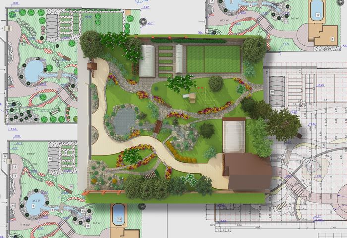 A site plan offers a detailed layout of the construction area. It includes information on current structures either on or adjacent to the project site, like nearby roads and buildings. The plan captures topographical features, which cover natural elements like landscaping and variations in terrain elevation. Additionally, site plans showcase intended modifications to the location post-construction, such as new drainage systems or topographical adjustments. For instance, if a shopping center’s construction location had neighboring structures, they would be depicted in the site plan.
3. PLOT PLANPlot plans and site plans share similarities in illustrating the entirety of a project location, usually from an aerial perspective. Yet, plot plans delve deeper into the specifics of the land on which the building will stand, highlighting details like land survey markers. They are commonly utilized to determine both the building’s boundaries and the complete extent of the acquired land. For instance, a plot plan might indicate space reserved for grassy areas on two sides of the proposed structure.
4. EXCAVATION PLANExcavation plan outline the location and measurements of the intended excavation for the project area. These designs can indicate the preferred method of excavation, be it trenching or otherwise. The depth, breadth, and span of the excavation are determined by the specific project and the conditions of the site. For instance, a residence with a basement or a commercial structure with underground parking would typically necessitate a more profound excavation compared to buildings without such features.
5. FLOOR PLAN
Floor plans provide an overhead view of a construction project, as if observing it without the roof. For multi-story structures, there’s typically a distinct floor plan for each level. These plans detail various features, including:• Measurements of both internal and external walls• Outdoor decks and patios
• The purpose of each room
• Material details
• Cabinetry and countertop placement & design
• Kitchen appliances and equipment locations
• Staircases and their orientation
For instance, in a two-story residence, an architect would typically draft a separate plan for each floor. The ground floor might showcase the kitchen specifics, while the upper floor would detail bedroom layouts.
6. REFLECTED CEILING DRAWING
A reflected ceiling drawing provides a depiction of the ceiling as if it were viewed from the floor below, essentially reflecting its design and features. These plans are invaluable tools for understanding the layout and aesthetic components of a ceiling. In a reflected ceiling plan, you might find details such as:
• Light fixtures and their positioning on the ceiling.
• Decorative elements like the intricate designs of crown molding.
• The specific ceiling construction, whether it’s a T-bar (suspended) ceiling or a hard lid made of gypsum board.
• Ventilation systems or air conditioning vents and their placements.
• Placement of smoke detectors, sprinklers, or other safety installations.
• Specialized acoustic or decorative panels and tiles.
• Potential drop ceiling areas or raised sections for architectural or functional purposes.
In essence, this plan offers a comprehensive view of the top-down design, ensuring that all elements harmoniously coexist and function optimally in the intended space.
7. ELEVATION DRAWING
 Elevation plan drawings present a structure’s vertical appearance, providing a straight-on view as if one were facing the building directly. Rendered in two dimensions, these plans don’t capture the depth or the three-dimensional aspects of a project but focus on its outward features.
Elevation plans play a pivotal role in showcasing the design intent for a building’s exterior facade. Whether it’s the preferred cladding material like brick, siding, or stucco, or a particular aesthetic theme, the elevation drawings would provide a detailed representation. Key aspects captured in these drawings include:
• Detailed specifications for exterior finishes and materials.
• Measurements and placements of exterior fixtures, emphasizing elements like doors, windows, and balconies.
• Decorative and architectural details, such as trim, columns, or archways.
• The roof’s pitch, type, and materials.
• Ventilation systems, gutters/downspouts, and other functional elements.
• Potential landscaping features or structures adjacent to the main building, like retaining walls.
In essence, elevation plans serve as a crucial reference for both architects and builders, ensuring that the envisioned facade is brought to life with accuracy and fidelity to the design intent.
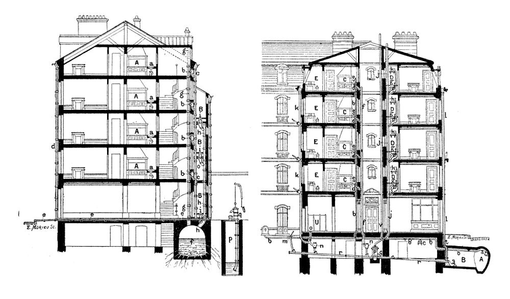
8. SECTION DRAWINGSection plan drawings provide a detailed vertical cut-through of a construction project, much like elevation plans. However, the distinction lies in their focus. While elevation plans give a snapshot of the building’s external appearance upon completion, section plans delve deeper, revealing the concealed architectural and structural elements behind the building’s facade.Section plans can unveil intricate details, such as:• The inner composition of walls or floors, revealing aspects like framing material/type, insulation, sheer, drywall type.
• The building’s foundational structure, which might include details of the footings, basement, or crawl spaces.
• Structural components like beams and columns, illustrating their size, material, and connection points.
• Headers, which are support elements placed above doors and windows, and their integration into the wall system.
• Roofing structures, including trusses, joists, and their respective insulation or ventilation systems.
• Staircase sections, detailing risers, treads, handrails, and support structures.
• Cross-sectional views of multi-story buildings, offering insights relating to and flow from one level to another.
Ultimately, section plans offer a holistic and layered view of the building, ensuring that architects, engineers, and builders have a thorough understanding of its internal complexities. This insight is vital not only for construction but also for future maintenance and modifications.
9. DETAIL DRAWINGDetail drawings magnify specific elements from general construction plans, enabling a closer and more comprehensive look. By presenting these components on a larger scale, detail drawings illuminate intricate aspects that might otherwise be overlooked, ensuring that each part is constructed with precision.These drawings are paramount for making clear precise specifications and connections of various components, providing clarity for the construction team. Architects and designers often craft detail drawings for:• Door & window frames: Showcasing the framework, sealing, and fastening methods.
• Staircases: Detailing the treads, risers, balusters, and handrail connections.
• Material connections: Demonstrating how various elements connect, such as the junction where a steel column meets the concrete foundation or how a beam connects to a column.
• Cornices: Highlighting decorative features near a wall’s top, including their design intricacies and attachment methods.
• Roofing details: Exploring junctions, overlaps, insulation layers, and waterproofing techniques.
• Jointing methods: Illustrating how two different materials might interface, ensuring a seamless and robust connection.
• Finishes and textures: Offering insights into surface treatments or decorative elements on walls, ceilings, or floors.
In essence, detail drawings act as a magnifying glass, providing a deeper dive into the finer points of construction elements. They bridge the gap between design intent and real-world construction, ensuring that every component aligns with the architect’s vision and meets structural and aesthetic standards.
10. MECHANICAL AND ELECTRICAL DRAWINGS
Mechanical and electrical (M&E) drawings lay out the blueprint for a building’s vital power and HVAC systems, detailing the intricacies of how these systems will be integrated into the structure. By mapping out these crucial components, M&E drawings ensure the building functions efficiently and safely.
Such drawings commonly detail:
• Thermostat Placements: Locations that offer optimal temperature control and user accessibility.
• Air Delivery Rates: Specifications ensuring adequate ventilation and air circulation.
• Ductwork Size and Locations: Demonstrating the pathway and dimensions for efficient airflow.
• Load Calculations: Ensuring electrical components can handle the building’s power demands.
• Switch Locations: Providing ease of access and logical placements for light switches, power outlets, etc.
• Wiring Size and Paths: Showing the planned route for electrical cables and the optimal wire gauge.
• Lighting Plan: Mapping out the positions of light fixtures, their types, and control mechanisms.
• Main Breaker Panels: Detailing their capacity, and connections leading outside to the main power grid.
The provision of these drawings often depends on the building’s scale and nature. For instance, commercial ventures, particularly those like restaurants, necessitate intricate ventilation and power systems. Therefore, construction plans for such establishments almost always incorporate detailed M&E diagrams. On the other hand, while residential properties may not always mandate such comprehensive plans, they are invaluable. Having detailed M&E drawings ensures more accurate cost estimates, helping homeowners avoid unexpected expenses. Furthermore, they act as a guidepost for contractors, ensuring the systems are installed correctly, efficiently, and safely. In all scenarios, it’s prudent to request these drawings from your architect or designer, safeguarding both your investment and the building’s occupants.
11. PLUMBING AND DRAINAGE Plumbing and drainage drawings delineate the comprehensive blueprint of a building’s water management system. They are paramount to guaranteeing a seamless flow of water into, within, and out of a structure, thereby ensuring optimal functionality and preventing potential water-related issues.An effective plumbing and drainage design not only ensures a dependable water supply but also safeguards against potential calamities like sewer backups, inadequate water pressure, or gas leaks. These drawings are comprehensive, detailing:• Underground Pipes: Illustrating their depth, material, diameter, and the route they take beneath the structure.
• Vents inside Walls and Attic Spaces: Indicating their positions and sizes, crucial for maintaining the right atmospheric pressure in the drainage system.
• Hot/Cold Water Lines: Demonstrating their path, ensuring consistent water temperature and pressure throughout the building.
• Water Heater Details: Apart from the manufacturer and model, these may also show the heater’s capacity, energy source, and proposed installation site.
• Gas Lines: Mapping their route and connections, ensuring safe and efficient delivery of gas for heating or cooking.
• Water Softeners/Filters: Highlighting their locations and specifications, essential for improving water quality.
• Bathroom & Kitchen Fixtures: Detailing their placements, models, and any specific installation guidelines.
In addition to these elements:
• Sewage System: Detailing the flow path to the main sewer line or septic tank, including gradient details for proper wastewater movement.
• Waste and Overflow Systems: Indicating positions for overflow pipes and potential drain points, vital for flood prevention.
• Faucets and Fittings: Providing specifics on types, models, and the preferred installation methodology.
• Rainwater Harvesting Components: If applicable, showcasing storage tanks, filtration systems, and distribution lines.
In essence, these plumbing and drainage plans act as a cornerstone for builders, ensuring that the building’s water and waste management system is designed and executed with precision. Proper planning in this phase ensures longevity and functionality while minimizing maintenance hardship.
12. STRUCTURAL PLANA structural drawing is a plan or set of plans and details for how a building or other structure will be built. Structural drawings are prepared by licensed and insured professional engineer, and based on information provided by architectural drawings. The structural drawings are primarily concerned with the load-carrying members of a structure. They outline the size and types of materials to be used, as well as the general demands for connections. They do not address architectural details like surface finishes, partition walls, or mechanical systems. The structural drawings communicate the design of the building’s structure to the building plan checker for review. Structural drawings are also included with a proposed building’s contract documents, which guide contractors in detailing, fabricating, and installing parts of the structure.
13. TITLE 24 (California Only)The California Title 24 Building Energy Efficiency Standards are designed to ensure new and existing buildings achieve energy efficiency and preserve outdoor and indoor environmental quality. These measures (Title 24, Part 6) are listed in the California Code of Regulations. The California Energy Commission is responsible for adopting, implementing and updating building energy efficiency. Local city and county enforcement agencies have the authority to verify compliance with applicable building codes, including energy efficiency. The Building Energy Efficiency Standards are updated every three years.
14. FINISH DETAILS
Finish drawings zoom in on the nuanced design elements that give a building its distinct character and aesthetic appeal. Unlike detail drawings, which concentrate on the essential structural components, finish drawings underscore the ornamental and functional design features that culminate in the final appearance and feel of the space.While detail drawings provide specifics like door and window frames’ construction, finish drawings delve deeper into:• Floor Finishes & Patterns: Highlighting materials like hardwood, tile, or carpeting, and specifying any intricate design patterns, inlays, or borders.
• Drywall Texture & Finishes: Detailing the type of texture, be it smooth, knockdown, or orange peel, and any special finishes or treatments.
• Ceiling Types: Differentiating between various ceiling styles, from suspended drop ceilings with tiles to hard lid gypsum board ceilings, and possibly including decorative elements like coffers or beams.
• Wall Paint: Not only specifying the color but also the finish—whether matte, satin, semi-gloss, or gloss—and any special treatments or patterns, such as accent walls or stenciling.
• Cabinet and Countertop Finish and Material Type: Indicating the kind of wood or other material for cabinets, the finish (painted, stained, or laminated), and the type of countertop, be it granite, quartz, marble, or laminate.
Expanding further, finishing drawings can also encompass:
• Door and Window Treatments: Including drapes, blinds, shutters, or any specialized glazing or tinting for windows and detailing door hardware and handles.
• Light Fixtures & Fittings: Showcasing the design, material, and positioning of chandeliers, sconces, pendant lights, and other fixtures.
• Plumbing Fixtures: Detailing the design and specifications for faucets, sinks, bathtubs, and showers.
• Built-in Furniture: Describing custom built-in units like bookshelves, wardrobes, or entertainment centers.
Ultimately, finishing drawings serve as a guidebook for interior designers, contractors, and millwork contractors, ensuring that the design vision comes to fruition in the exacting manner intended, harmoniously blending form and function.
15. DOORS AND WINDOWS SCHEDULE
 Window and door schedules serve as detailed blueprints that streamline the process of selection, placement, and installation of these integral architectural elements. They encompass comprehensive data essential for contractors to ensure accuracy in fitting, aesthetics, and functionality.
In addition to simply identifying the distinct types of windows and doors designated for a building, and their precise locations, these schedules delve into:
• Dimensions & Specifications: Providing exact measurements for both the openings and the units themselves, including width, height, and depth, which are crucial for a seamless fit.
• Material Types: Describing the materials used for the frame and pane, such as vinyl, wood, aluminum, or fiberglass for windows, and wood, metal, or glass for doors.
• Glazing Details: For windows, offering specifics about the type of glass, be it tempered, frosted, tinted, or double-glazed, and any energy-efficient coatings or treatments.
• Hardware Specifications: Cataloging the types of handles, hinges, locks, and other hardware, including their finishes – for instance, brushed nickel, chrome, or antique brass.
• Operational Features: Highlighting how the window or door functions, such as sliding, casement, awning, pivot, or folding.
• Finishes & Treatments: Indicating any special finishes, stains, or paint colors to be applied.
• Thermal & Acoustic Properties: Detailing any insulative properties or soundproofing capabilities, especially relevant for specific environments or climates.
• Safety and Security Features: Outlining any reinforced structures or lock mechanisms that ensure added security or safety compliance.
• Accessories & Additional Features: Mentioning any supplementary elements like insect screens, weatherstripping, or decorative panels.
By incorporating these intricate details, window and door schedules offer a robust guide to contractors, ensuring that these architectural components are not only aesthetically pleasing but also meet the building’s functional and safety requirements.
16. PERSPECTIVE DRAWING OR 3D RENDERINGPerspective drawings breathe life into architectural designs by offering a three-dimensional representation of a proposed structure. Going beyond just a flat, two-dimensional outlook, these drawings enable viewers to grasp the depth, scale, and volumetric relationships within a design.These illustrations serve multiple purposes:1. Enhanced Visualization: By presenting a project in 3D, perspective drawings offer a clearer image of how different facets of the building will merge and interact, both internally and externally.
2. Space-related Awareness: Such drawings make clear the space dynamics and depth, allowing stakeholders to understand room sizes, corridors’ widths, and the relative positioning of various architectural elements.
3. Material and Finish Preview: Through color, shading, and texture, perspective drawings can provide a preliminary glimpse into the materials and finishes intended for the project. This helps in visualizing how brick might contrast with wood, or how sunlight might play on certain surfaces.
4. Landscaping & Environment Integration: By including surroundings, these drawings can depict how a structure sits within its environment, be it an urban setting, a suburban neighborhood, or a natural landscape. This offers insight into aspects like landscaping, walkways, and how the building complements or contrasts with its surroundings.
5. Stakeholder Communication: Perspective drawings are invaluable tools for architects and designers to convey their vision to clients, contractors, and other stakeholders, ensuring everyone shares the same conceptual understanding.
6. Continuous Design Refinement: With a more immersive view, potential design challenges or aesthetic improvements can be identified early, allowing for refinements before actual construction commences.
7. Marketing & Promotion: For commercial projects or real estate developments, these drawings can be used in promotional materials to attract potential buyers or tenants by showcasing the envisioned end result.
In basic terms, perspective drawings bridge the gap between technical design and tangible reality, ensuring everyone involved in a construction project has a comprehensive and vivid understanding of the final objective.
CONCLUSION
Having a full set of plans for any construction project is crucial for a myriad of reasons:
1. Clarity and Vision: Plans provide a visual representation of the final outcome. They help all stakeholders, from architects to builders to clients, understand the scope, scale, and aesthetics of the project.
2. Budgeting: With clear plans, estimators can provide a more accurate budget. Unexpected costs can be minimized as the requirements, materials, and labor are all detailed from the outset.
3. Efficiency: A full set of plans ensures that all construction activities are well-coordinated. Workers know precisely what needs to be done, when, and in what order, leading to smoother operations and time savings.
4. Safety: Comprehensive plans take into account safety measures, ensuring that the structure is sound and adheres to local building codes. This reduces the risk of accidents during construction and ensures the long-term safety of the building’s occupants.
5. Regulatory Approval: Most local authorities require a detailed set of plans before granting construction permits. These plans ensure that the construction complies with local building regulations and zoning laws.
6. Mitigation of Disputes: Having a detailed plan minimizes ambiguities. In case of disputes, stakeholders can refer back to the plans as a point of reference, ensuring everyone is on the same page.
7. Sustainability and Environment: Modern construction often integrates sustainable solutions. Plans ensure that these are correctly incorporated, from green technologies to efficient waste management.
8. Quality Control: Plans serve as a benchmark for quality. Contractors can compare ongoing work with the plans to ensure it meets the desired standards.
In summary, a full set of plans is the foundation upon which successful, safe, and efficient construction is built, ensuring that the project’s vision becomes a tangible reality.
